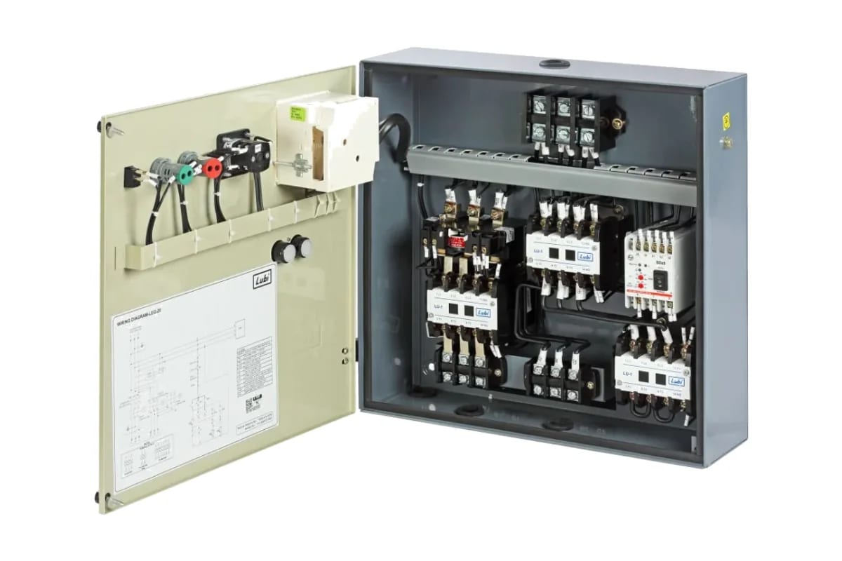
Short answer: a star delta starter uses three contactors and a timer. The motor starts in star (main + star contactors), which cuts starting current to about one-third of DOL. After a few seconds the timer drops the star contactor and closes the delta contactor, and the motor runs at full voltage.
Star delta starter power diagram

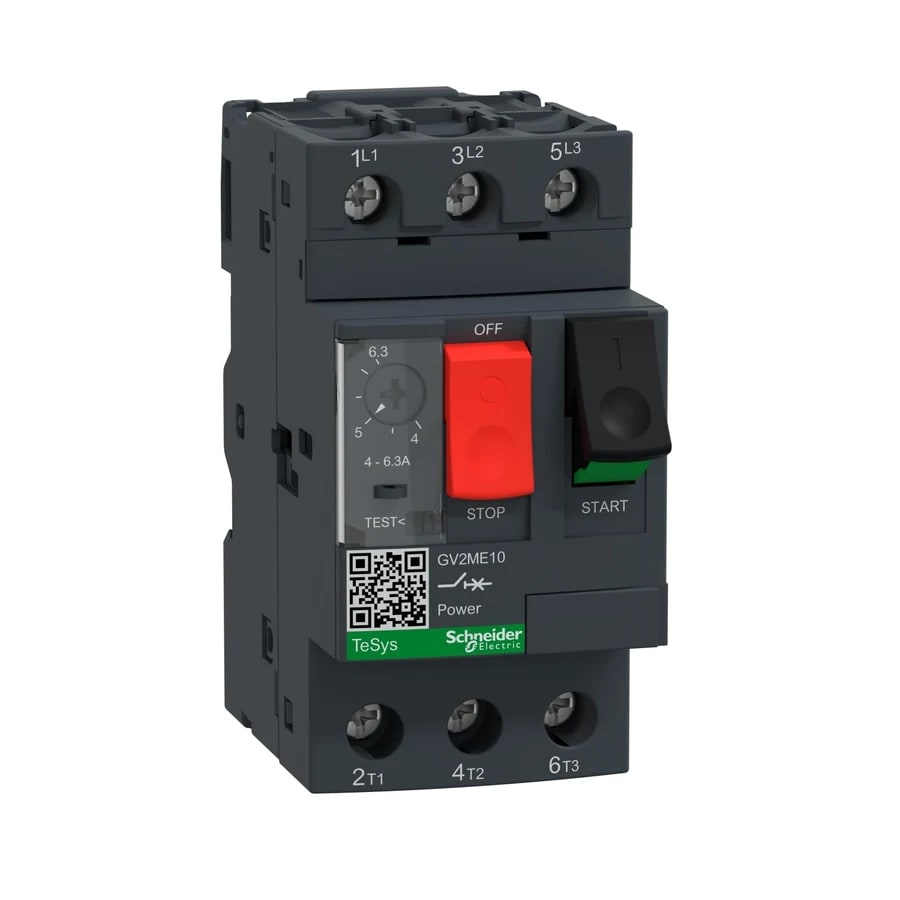
The supply passes through the short-circuit protection (MCCB or MPCB), the main contactor KM1 and the overload relay to the motor terminals U1, V1 and W1. The other ends of the windings (U2, V2, W2) go to the star contactor KM2, which shorts them together, and to the delta contactor KM3, which connects them back to the supply so that U1-W2, V1-U2 and W1-V2 form the delta.
Star delta starter control diagram with timer

Sequence of operation
- Press Start S2: KM1 (main), KT (timer) and KM2 (star) energise. KM1 13-14 holds the circuit after S2 is released.
- The motor accelerates in star. Each winding sees 1/√3 (about 58%) of line voltage.
- When the timer runs out, KT 15-16 opens and KM2 drops out.
- KT 15-18 closes and KM3 (delta) picks up through the KM2 21-22 interlock. The motor now runs in delta at full voltage.
- Stop S1 or the overload contact 95-96 de-energises every coil.
Components and settings
Item | Typical choice | Note |
|---|---|---|
Main contactor KM1 | AC-3 rating ≥ 0.58 × motor FLC | Carries phase (winding) current |
Delta contactor KM3 | AC-3 rating ≥ 0.58 × motor FLC | Carries phase current |
Star contactor KM2 | AC-3 rating ≥ 0.33 × motor FLC | Often one frame smaller |
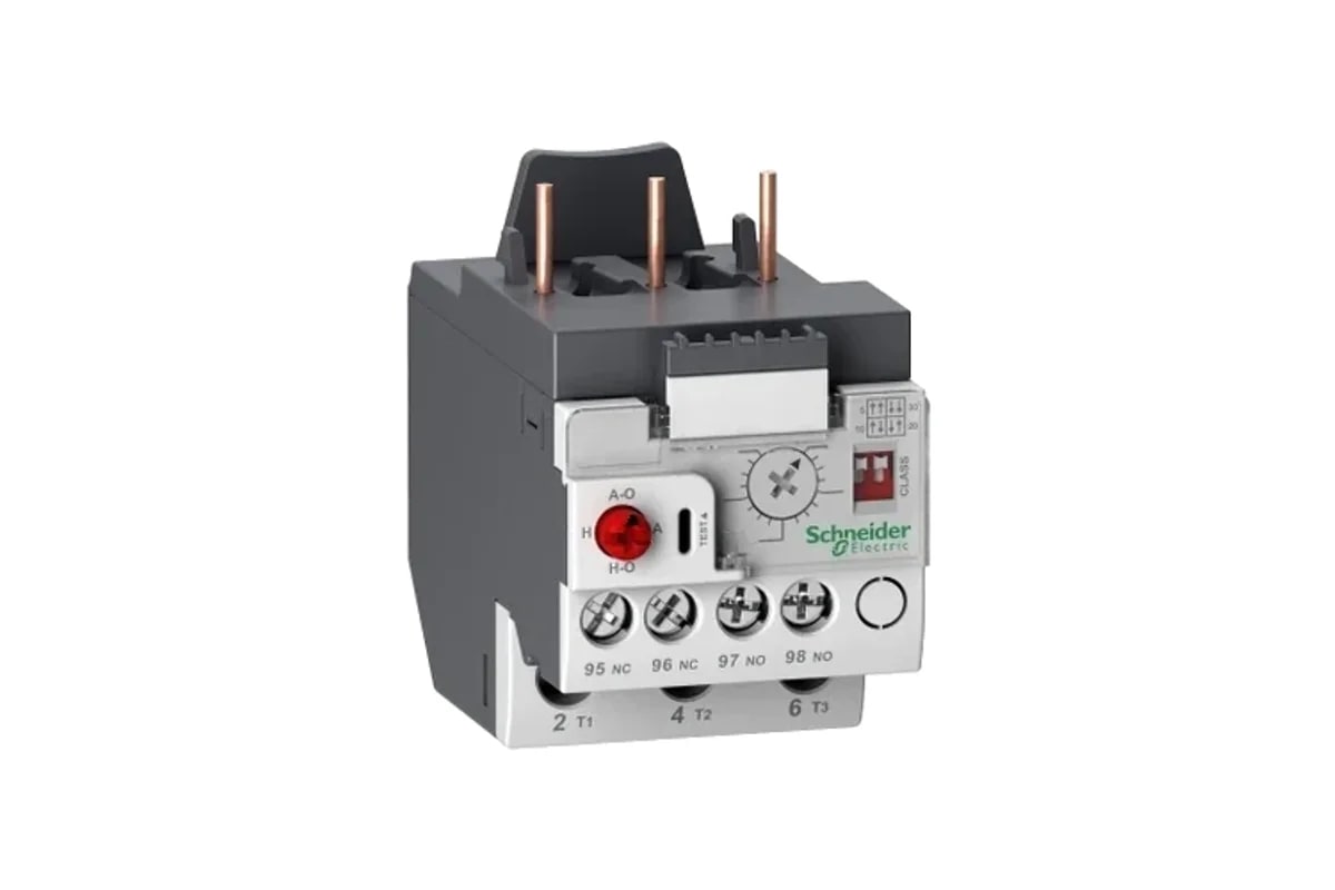
Overload relay | Set to 0.58 × motor FLC | When fitted in the winding circuit after KM1 |
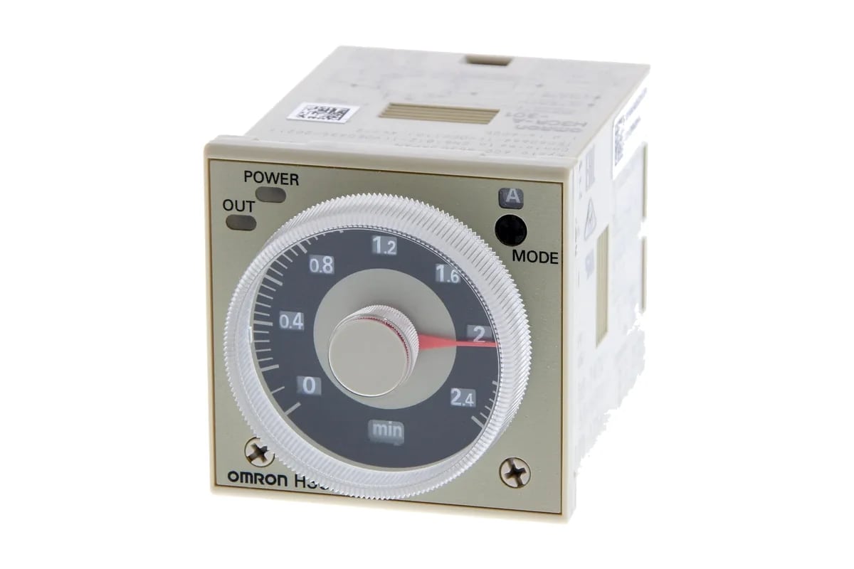
Timer KT | Star-delta timer with changeover pause | Set so the motor is near full speed in star |
Protection | MCCB or MPCB | Coordinated with the contactors |
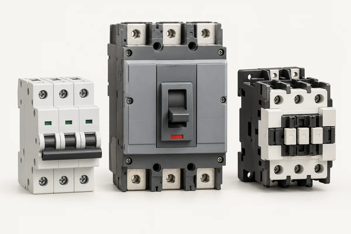
Choose contactors from contactors and overload relays and the timer from timer relays. Ready units are on star delta starters; custom enclosures with meters and indication are on star delta starter panels.
When to use star delta
- Motors that start on light load: centrifugal pumps, fans, compressors starting unloaded.
- Six-terminal motors rated for delta at line voltage (for example 415 V Δ).
- Where supply limits or the utility restricts DOL starting current.
For heavy starting loads, or to avoid the current dip at changeover, compare a soft starter or VFD in DOL vs star delta vs soft starter.
Star delta sizing example
For a 415 V delta-connected motor with a nameplate full-load current of, say, 55 A:
Part | Rule | Result |
|---|---|---|
Main contactor KM1 | 0.58 × FLC | AC-3 ≥ 32 A |
Delta contactor KM3 | 0.58 × FLC | AC-3 ≥ 32 A |
Star contactor KM2 | 0.33 × FLC | AC-3 ≥ 18 A |
Overload relay (after KM1) | 0.58 × FLC | Set at about 32 A |
Two 3-core cables run from the starter to the six motor terminals, each sized for the phase current. Check the maker’s star-delta coordination table before finalising.
Open vs closed transition
The standard starter is open transition: the motor is disconnected for a short pause between star and delta, which can cause a current and torque spike at changeover. Closed-transition starters add a resistor stage to keep the motor connected, at extra cost. A soft starter or VFD avoids the step altogether.
Advantages and disadvantages of a star delta starter
Advantages | Disadvantages |
|---|---|
Starting current about one-third of DOL | Starting torque also falls to about one-third |
No extra power components beyond contactors and timer | Needs a six-terminal motor and two motor cables |
Widely understood and easy to service | Current spike at changeover in open transition |
Lower cost than a soft starter for many ratings | Not suitable for loads that start heavily loaded |
Common faults
- Motor does not change to delta: timer coil, KT contact or KM2 interlock fault.
- Both contactors chatter or trip at changeover: timer set too short, or missing changeover pause.
- Overload trips in run: overload set to full FLC instead of 0.58 × FLC, or wrong position.
- Motor runs hot or noisy: wrong terminal connection at U2, V2, W2, so the delta is formed incorrectly.
Sources
- IEC 60947-4-1 (adopted in India as IS/IEC 60947-4-1): contactors and motor starters
Related: DOL starter diagram, contactor selection guide, what is a contactor, motor starters and the motor control and starters category.
Frequently asked questions
How many contactors are used in a star delta starter?
Three: main, star and delta, plus a timer and an overload relay.
What is the overload setting in a star delta starter?
About 0.58 × motor full-load current when the relay is in the winding circuit after the main contactor.
How much does star delta reduce starting current?
To about one-third of the DOL starting current, with starting torque also reduced to about one-third.
What timer setting is used?
Usually a few seconds, long enough for the motor to reach near full speed in star.
Why is a star delta starter used?
To reduce starting current. In star each winding gets about 58% of line voltage, so starting current and torque fall to about one-third of a direct-on-line start.
Can a star delta starter start a motor on load?
Only light loads. Starting torque is about one-third of DOL, so heavily loaded starts can stall in star or cause a large current spike at changeover; use a soft starter or VFD instead.
How many wires go from a star delta starter to the motor?
Six power conductors (U1, V1, W1 and U2, V2, W2), usually as two 3-core cables, plus the earth.
Specify your requirement
Send the rating, make, quantity and delivery location. Attach the drawing or datasheet where available.
Request a quote Or send it on WhatsApp ↗