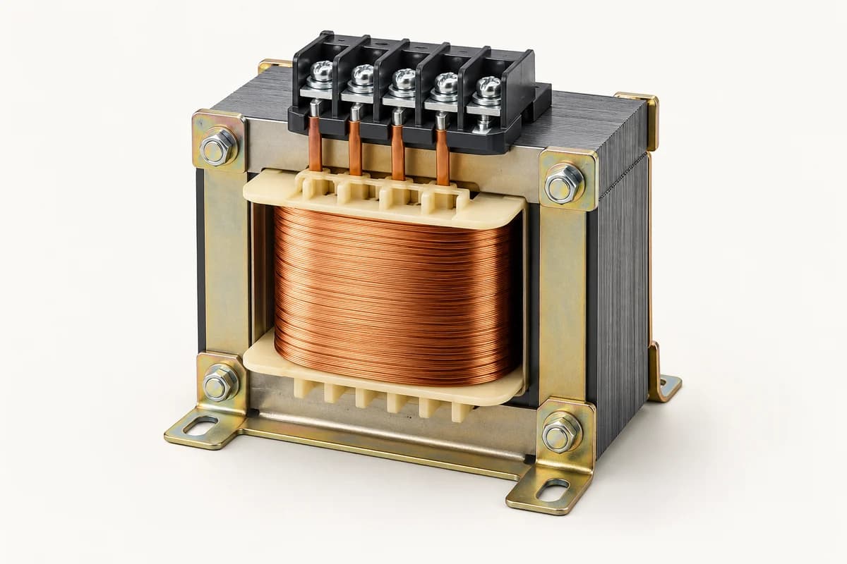
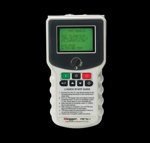
What a turns ratio test checks
A transformer turns ratio test checks whether the measured relationship between windings agrees with the expected ratio for the transformer’s connection and tap position. A TTR instrument applies a controlled test signal and evaluates the resulting voltage relationship. The result can help investigate tap changer issues, incorrect connections, shorted turns or inconsistencies between the nameplate and the asset.
The test is one part of transformer assessment. It does not measure winding insulation resistance, oil condition or the complete mechanical state of the transformer. For a purchase enquiry, define which transformer types and winding arrangements the instrument must support, and identify the project’s test procedure before choosing a model.
Read the nameplate and connection diagram together
The nameplate supplies rated voltages, vector group and tap information. The connection diagram explains how the windings are arranged and how those voltages relate to the instrument’s measurement. On a three-phase transformer, line-to-line voltage ratio and individual winding turns ratio are not always numerically identical. Star and delta connections change the relationship that the calculation must account for.
This is why a ratio entered without its vector group can generate an incorrect expected value. Confirm how the instrument recognises or handles the specified connections, phase displacement and polarity. Special transformers, multiple windings and unusual vector arrangements need explicit compatibility checks. A statement that the tester is three phase is insufficient for every transformer configuration.
Keep tap position with every result
Changing the tap changes the expected ratio. Record the actual tap position, nameplate information, tested winding pair and phase identification with each measurement. An engineer can then compare like results across phases and across maintenance visits. A result assigned to the wrong tap can look like a transformer fault even when the measurement itself was repeatable.
Consider an asset whose nominal rated voltage ratio is 25 at its principal tap. A neighbouring tap has a different specified ratio. Comparing both measurements with 25 would mislabel the second result. For a star-delta unit, the winding connection also affects the expected phase relationship. Use the approved nameplate and instrument calculation rather than carrying a nominal ratio across the whole tap table.
What an unexpected ratio can mean
A difference from the expected value calls for review of the test setup, selected vector group, nameplate entry and tap position before diagnosing the asset. Poor contact or incorrect lead identification can distort the result. A repeatable discrepancy after those checks may justify further investigation under the transformer manufacturer’s procedure. Do not apply one universal percentage tolerance to every transformer and test arrangement.
Excitation current and phase angle, when measured by the chosen instrument, can provide additional information. Their interpretation also depends on transformer construction and the procedure. Keep the complete report with the measured ratio and expected value so that an engineer can distinguish a data-entry problem from evidence requiring further transformer tests.
Specify the meter’s actual capabilities
Compare ratio range and accuracy across the required range, excitation options, supported vector groups, single-phase and three-phase workflows, lead sets and reporting functions. Megger’s TTRU3 is a documented example of a true three-phase instrument. Its capabilities belong to that model; a different instrument in the same supplier category may use a different test sequence or have a narrower application.
Check operation with the site power supply or battery arrangement, field portability, cable lengths and access to the transformer terminals. Software should preserve asset identity, tap data and the test configuration. If an acceptance procedure specifies a particular measurement method, ask the proposed manufacturer to confirm compliance with that method and disclose limitations.
Prepare the quotation and testing plan
TPE lists transformer turns ratio meters for one- and three-phase applications. Send the transformer nameplate and connection diagram, winding pairs, vector groups, tap schedule, expected ratio range and reporting specification. Include special transformer duties, preferred make, required accessories, quantity and calibration-document requirements. These inputs let the supplier compare a proposed meter against the actual assets.
Transformer testing requires competent personnel, authorised isolation and the manufacturer’s safety procedure. Stored energy, induced voltages and connections to other equipment must be addressed in the test plan. This purchasing guide does not provide terminal connection instructions. The selected instrument’s manual and the asset procedure determine the approved arrangement, including how equipment is made safe before and after the test.
Related products and buying guidance
Testing and measuring equipment
Request an equipment quotation
Sources and further reading
Frequently asked questions
Is a voltage ratio always the same as turns ratio?
For three-phase transformers the relationship depends on winding connections. Use the vector group and connection diagram when determining the expected result.
Should every tap have the same ratio?
No. Tap changes alter the expected ratio. Record the position and compare with the specified value for that tap.
Does TTR replace other transformer tests?
No. Ratio testing addresses a particular winding relationship. Insulation, resistance and other condition checks assess different properties.
Specify your requirement
Send the rating, make, quantity and delivery location. Attach the drawing or datasheet where available.
Request a quote