Choose the meter for the resistance measurement
A micro-ohm meter measures very low resistance in components such as electrical joints, conductors and switching contacts. Select it by the asset’s prescribed test method, required resistance range, accuracy and test current. A higher maximum current does not by itself make one model suitable for every low-resistance measurement. Winding measurements add requirements that a contact-testing instrument may not support.
The name micro-ohm describes the scale of resistance being investigated. It gives little information about lead arrangements, continuous duty, inductive-load capability or the data stored in a report. Those differences matter when a maintenance team compares bids for a single instrument expected to cover several kinds of equipment.
Why four-wire measurement matters
With a two-wire resistance measurement, lead and contact resistance contribute to the reading. Those contributions can be significant compared with a low-resistance joint. A four-terminal or Kelvin method separates the current path from the voltage-sensing connections. The instrument measures the voltage drop across the defined part of the specimen and calculates its resistance from the test current.
The connection geometry still matters. A report should identify the measured path and contact positions so that the next test examines the same portion of the assembly. Probe quality, access to the conductor and repeatability affect the evidence. Ask whether the supplied leads and clamps suit the actual equipment, rather than budgeting for the instrument alone.
Current, range and thermal effects
Use the current required by the asset procedure and confirm that the selected instrument can deliver it through the expected circuit resistance. Check duty cycle and lead limits. A catalogue’s maximum current may apply only to particular ranges or operating modes. Resolution is the smallest displayed increment; accuracy describes how closely the result represents the measured quantity. Both need review.
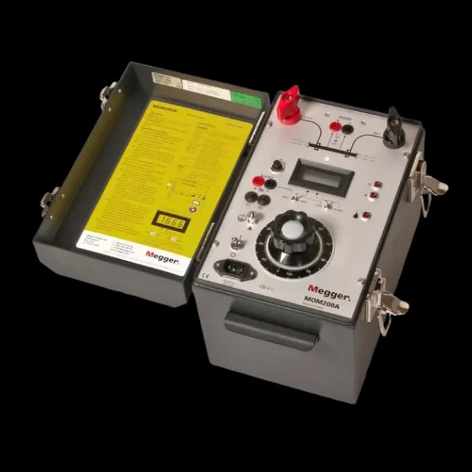
Thermal electromotive forces at dissimilar-metal junctions can influence very small voltage measurements. Forward and reverse current measurements can help compensate for those effects when supported by the instrument and method. Megger’s DLRO10 and DLRO10X documentation describes automatic current reversal. This is a documented feature of that family, not a feature to assume on every micro-ohm meter.
Separate contact testing from winding testing
A transformer winding is an inductive load. Current stabilisation, stored energy and controlled discharge affect the measurement and safe operation. A meter intended mainly for contacts may have restrictions on inductive circuits. Confirm winding capability, stabilisation indication and discharge arrangements in the exact model manual. An instrument’s electrical protection rating does not authorise a live measurement.
For example, a purchaser might need to trend busbar joint resistance during a shutdown and also measure transformer winding resistance. These are two defined duties. The quotation should state which model supports each procedure, what leads are supplied, and whether separate equipment is required. An unexplained substitution can otherwise leave the winding task outside the instrument’s intended application.
Compare reports and ownership requirements
A low reading needs context: conductor temperature, measured length, connection positions and the manufacturer’s limits can all affect interpretation. Phase comparison and historical trend information may help an engineer investigate changes, but a numerical difference does not identify a loose joint by itself. Retain the original readings and conditions instead of reducing the record to a single pass label.
Check battery operation or mains requirements, operating environment, case protection, lead length, storage capacity and software compatibility. If the team works across several sites, confirm how records are assigned to assets and transferred into the maintenance system. Include calibration documentation and the required accessories in the comparison so that a cheaper instrument-only offer is not mistaken for a complete kit.
Send a useful quotation request
TPE’s catalogue includes micro-ohm meters and low-resistance measuring bridges. State the assets to be tested, prescribed current, expected resistance range, inductive-load requirement, test frequency and reporting needs. Attach the project specification or relevant extract of the equipment manual. Request confirmation of measurement accuracy at your range and operating conditions.
List clamp or probe style, lead length, quantity, calibration requirements and any preferred model. Ask the supplier to identify deviations from the specification. Measurements should be planned and performed by competent personnel on equipment made safe under the authorised procedure. The purchase specification should leave enough detail for the maintenance engineer to confirm that the instrument and accessory set suit that work.
Related products and buying guidance
Testing and measuring equipment
Request an equipment quotation
Sources and further reading
Frequently asked questions
Can a multimeter replace a micro-ohm meter?
A general multimeter may lack the resolution, accuracy and four-wire arrangement required for very low resistance. Compare the required procedure with the exact meter specification.
Is more test current always better?
No. Current must suit the asset procedure, instrument duty, leads and measured circuit. Maximum output alone is not a selection rule.
Can every micro-ohm meter measure transformer windings?
No. Confirm inductive-load capability, stabilisation and controlled discharge in the exact model manual.
Specify your requirement
Send the rating, make, quantity and delivery location. Attach the drawing or datasheet where available.
Request a quote